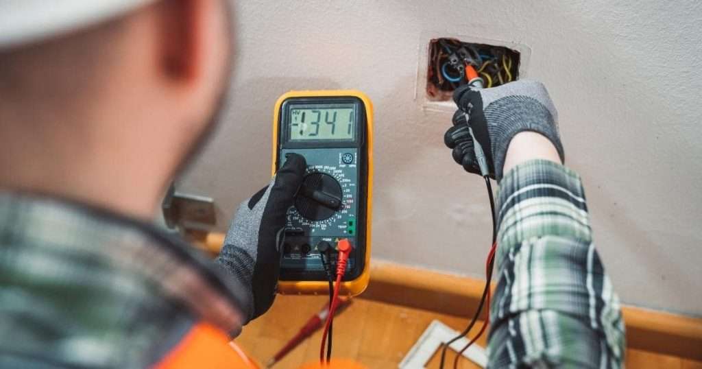
It’s pretty easy to test the ground with a multimeter. We measure voltage from live to the ground and live to neutral wires and evaluate ground connection with the voltage difference.
Grounding or earthing is an essential safety precaution that protects you from electrocution and provides a path for current flow through a wire to the ground instead of your body. Your life and appliance are always at risk in an improperly grounded system.
In this post, you’ll learn how to test a ground wire in your house and vehicles to evaluate ground connections.
How to test the ground with a multimeter
To test if an outlet or circuit is grounded, we measure the voltage difference from live to the ground and live to neutral wires with a multimeter and their voltage difference.
Follow some quick steps below.
- First, identify wires with their color code.
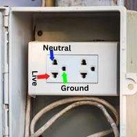
- In a 3-prong receptacle, a single top or bottom hole is for the ground wire. The left of two holes in a row is the neutral wire, and the right is the live wire.
- Now set your multimeter dial to AC voltage(ACV or A〜). Find voltage between
- Live and ground wire
- Live and neutral wire
- ground and neutral wire
A ground connection is excellent if the voltage between the Live-ground wire and the Live-neutral wire is the same, such as around 120 or 140V. Also, ground and neutral wire voltage should be nearly equal to zero.
Below we have explained step-by-step to test ground connection in any circuit with your multimeter.
Step 1: Safety Measures
As we have to work with high-voltage wires, it’s essential to have safety precautions first. Never work on live wires barehanded. You must be wearing shoes and insulated gloves.
Step 2: Identify Live, Neutral, and Ground Wires
To test ground, we have to measure voltage between wires, and it’s necessary to identify wires before we proceed.
- Identify with wire code.
You can identify wires by their color by removing the outlet cover. If your home wiring is done in a standard way, green or green with a yellow stripe is ground wire, blue or white is neutral, and the red, black, or brown wire is live.
- Identify with standard wiring pattern in Receptacle
In another way, if your receptacle holes are A-shaped (3 prongs), the single upper hole is for the ground, the left is neutral, and the right is a live wire terminal. If your socket holes are in a V shape, then live is at left, and neutral is at right.
Step 3: Set up your multimeter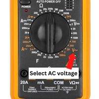
After identifying wires, set up your multimeter. Insert the red probe on the port with the VΩmA sign and the black probe inside the COM-labelled port.
Turn the multimeter dial to AC voltage marked with ACV or V〜 because the home power supply is AC. Select a higher range in the AC voltage setting, such as 600 or 750V, as house wiring carries a massive amount of current.
Step 4: Connect the Probes and measure the voltage
To evaluate ground wires, we check the voltage difference between
- Live and ground wire
- Live and neutral wire
- Ground and Neutral wire
Connect the red probe to the live wire and the black probe to the neutral and ground wire one by one and note down both readings. After that, detach the probe, connect them to neutral and ground wires, and note the third reading.
Step 5: Evaluate the Results
- If a circuit is grounded, the voltage reading between live and ground should be near 120 or 240 (depending on power distribution).
- If the ground and live wire voltage decrease by more than 5 volts than the live and neutral wire voltage, your ground connection is faulty, causing current leakage.
- And if the multimeter reads zero voltage between live and ground wire, the ground wire is not installed or connected, either in the socket or the entire building.
- Also, the neutral-to-ground reading should be nearer to zero.
Remember: If your circuit or outlet is ideally grounded, your multimeter must read 120 or 240 volts between live-neutral and live-ground.
How to test car ground wire with a multimeter

To test ground wires in cars, measure voltage between battery and ground points with a multimeter.
Follow the quick steps below:
- First, locate all ground points or wires that we have to test.
- Connect the red probe to the positive battery terminal and the black probe to each ground point, such as on the chassis.
- Test each ground connection while the engine is off and after starting the engine. You will see voltage increases after the engine is on.
- The voltage between the battery positive and all ground connections should be the same.
- If voltage decreases in a ground connection than the other ground reading, voltage is leaking through the faulty ground wire of a component.
To examine your car’s ground wires and circuit, follow this simple detailed guide below:
-
Locate the ground Wires in your car
Before starting the test, you must locate ground connections in your cars. Many components of vehicles are grounded to the chassis with bolts.
You can find them on the chassis, driver, and passenger side fender, near the engine block, shock tower, and ECU. You can also find your car’s ground points in the manufacturer’s manual.
-
Set your multimeter
As batteries always provide DC, set your multimeter to the DC voltage setting, denoted by DCV or V, with dots over a straight line. Set the range above the battery voltage.
For example, if your car has a 14-volt battery, select the closest upper voltage range on your multimeter, such as 20 volts.
-
Test voltage while the engine is off
First, connect the red (+ve) probe to the positive terminal and the black probe(-ve) to the battery’s negative terminal and note the battery voltage.
Now measure the voltage between the battery-positive terminal and every ground point on the chassis. Testing the voltage between the positive battery terminal and ground points will help you know if the ground points are efficient or leaking. Connect the red probe to the positive battery terminal and the black probe to the bolt of every ground connection, and remember the reading.
-
Measure voltage during the engine is on.
After you have tested the voltage on the switched-off engine, start the engine and perform the same voltage test. Measure the voltage between the battery-positive terminal and all ground connections.
Connect the red probe to the positive battery terminal and the black probe to the bolt of every ground connection, and remember the reading.
After you start the engine, the voltage increases to a few points, such as 12.2 to 12.5 volts.
-
Evaluate the result
- If the ground wire is fine, the voltage between the battery positive terminal and each ground point should be the same, such as 12.5 V.
- A ground connection leaks if the voltage at any connection drops more than .4 volts than others. While the engine is switched on, you may see a fluctuating voltage reading on the multimeter, identifying a poor ground connection.
- To examine a faulty ground connection, measure voltage in the ground wire from the negative battery terminal and the ground spot where voltage drops.
Check out how to measure resistance in ground wires below:
Test resistance in ground Wires
Another way to evaluate the ground connection is by measuring the resistance between the battery negative terminal and the ground connection. By measuring resistance, we can determine the quality of wires and if they are efficiently passing current.
As the ground wire is connected to the battery’s negative terminal, we use the negative terminal instead of the positive.
Set your multimeter to resistance ‘Ω‘ mode. Connect one probe to the negative battery terminal and the other probe to each ground connection one by one (ground connection at chassis).
Evaluate Result
Ground wires are in good condition if the multimeter reads minimum resistance, such as near 0, because less resistive force means excellent current flow.
If ground wire resistance is relatively high, wiring is faulty, and current is not efficiently passing.
How to test ground without a multimeter?
Use a bulb holder(socket) to test a ground connection. Insert socket wires in the live, and the neutral hole of the receptacle bulb will glow.
Now insert wires in the live and ground hole of the outlet. If the bulb lights, the ground is available; otherwise, there is no ground connection.
Conclusion
If your circuit is properly grounded, it could be life-saving. Everyone should test ground connections in their building every couple of months.
You don’t have to be a pro electrician to test the ground connection. Have preventive measures, and follow the simple steps explained above.
Related Posts