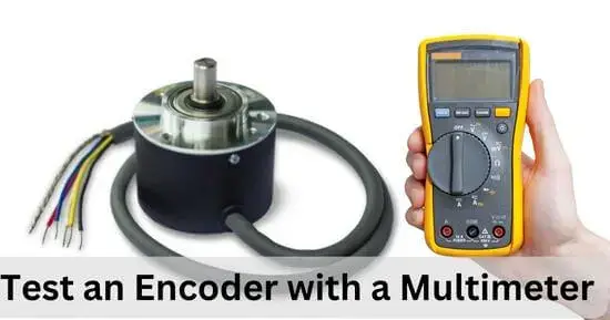
This guide provides a step-by-step process for test an encoder with a multimeter, which is suitable for both beginners and experienced technicians.The encoders identify any moving object’s position, direction, or speed.
These are used in so many different electrical hardware. The mechanism in which they work is complex, but their output is always in the form of some signal. This can be any optical, magnetic, electrical, or resistive signal.
So any material in which there is some relation of movement is available; the encoders are used there. So as an electrical gadget, there is a great possibility of its damage, and if the encoder gets damaged, then we will not be able to get productive feedback from it.
Types of encoders: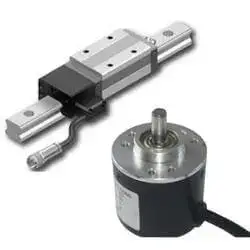
There are two types of encoders, and some of their specificities allow the engineers to choose which encoder should be installed in what kind of appliance. So the two major types of encoders are:
- Linear encoder:
This encoder is used for the transmission and detection of the position of a material. It means that it produces the electrical signal along with the changing position.
- Rotary encoder:
The rotary encoder is the one that uses the displacement and the value of movement of an object and produces feedback in the form of different signals. So it can be used in industries and electronics.
The rotary encoders are also called shaft encoders. There are two further types of rotary encoders.
- Absolute rotary encoders
- Incremental rotary encoders
How to test an encoder with a multimeter?
Using a digital multimeter to test the condition of an encoder can be a different task as, here, you have to measure the peak voltage value, frequency, and the average duty cycle-like measurements of the encoder by using the digital multimeter.
But you cannot measure the condition of the electrical signals in the encoder by using the digital multimeter. Although the deep inspection procedure requires this requirement to be also fulfilled, in the case of the multimeter, it is only possible to measure the value of the voltage, frequency, and duty cycle of the encoder.
If you have to understand the role an electric signal plays in the encoder, you have to go for other tools because the digital multimeter will not help you under this condition. Lets move forward on testing procedure.
Materials required:
- 12 volts Power supply source
- Digital Multimeter
- An encoder
Preventive measures:
Before starting the testing procedure of the encoder, you are advised to look at the installation menu given by the appliance company upon which you are going to perform an encoder test.
This precaution will help you to save yourself from any issues regarding the connections you have to make further in the test.
Starting the test after understanding the encoder’s whole structure will benefit you and help you save time and perform the test accurately.
How to test an encoder with a multimeter (quick guide):
- Connect the power supply with the encoder accurately
- Set the digital multimeter at the voltage settings
- Connect the leads of the multimeter with the pins.
- Keep rotating the shaft of the encoder
- Measure the value of voltage from the display screen of the digital multimeter.
- The resulting readings close to the normal voltage value of the encoder mean the encoder is not defective.
How to test an encoder with a multimeter (step-by-step guide):
Step 1: Connect the power supply
You will test the encoder using the digital multimeter, so you have to connect the encoder to the power supply of 12 volts. It will help the encoder get the voltage by which it will be easy to measure the exact voltage reaching the encoder from the multimeter.
You have to connect the positive power supply of 12 volts with the A pin of the encoder and the negative power supply to pin B.
After connecting the power supply now, you have to move towards the next time.
Step 2: Set the digital multimeter
To measure the voltage of the encoder with the digital multimeter, you have to set the digital multimeter at the voltage settings. For this, touch the selection knob of the digital multimeter and slightly rotate it towards the voltage so that it can measure the actual amount of voltage reaching the encoder.
Step 3: Connect digital Multimeter
Now you have to connect the digital multimeter with the encoder, so you have to take the positive lead of the digital multimeter and connect it with pin C then take the negative lead of the digital multimeter and connect it with pin B. After making the proper connection, now move towards the next step.
Step 4: Rotate the shaft
After connecting the digital multimeter with the encoder, you have to keep rotating the shaft on the encoder so that the value of the voltage on the display screen of the digital multimeter can change.
Step 5: Note the readings
You will get the voltage reading on the digital multimeter’s display screen. You have to note these readings and then compare them with the actual voltage reading of the encoder.
Step 6: Final Results
While rotating the shaft on the encoder, if the voltage readings fluctuate on the digital multimeter’s display screen, there is no default in the encoder.
Moreover, as you have applied the power source of 12 volts to the system, if the resulting voltage readings are lower than the 12 volts, it means that no effective amount of voltage is reaching the encoder, and it leads to the clear identification of the defective encoder.
Step 7: Troubleshooting of encoder
If you cannot reach trustworthy final results at the end of the testing of the encoder by using the digital multimeter and the resulting voltage readings are quite normal, then you have to check the condition of the electrical signals reaching the encoder, which would not be possible by using the digital multimeter.
So for this, you have to use the oscilloscope to understand the cause of the malfunctioning of the encoder.
Final verdict
The encoders are the electrical parts that work on a specialized movement control mechanism and allow the formation of the feedback signals by using the movement controls. Any problem in the signal transduction procedure of the encoder can lead to faulty feedback production.
The required testing and appropriate testing of the encoder are required to understand how you have to solve the problem that has occurred in the encoder. Using the digital multimeter, you will understand if any frequency and voltage-related problem has occurred in the encoder. Then, you can make it checked by a professional for further inspection.
More Guides: