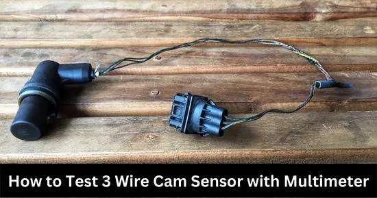
This article teaches how to test a 3-wire Cam sensor with a multimeter. A bad cam sensor can make the engine lose power, poor mileage, staling, and slow acceleration. Thus, the cam sensor should be tested with a multimeter and other sensors.
The camshaft and crank sensors share the crankshaft drive position and rotation with the ECU, which is used for ignition. The ECU then uses the information to inject fuel properly and ignite the spark plugs at the correct time.
Engine performance will suffer if a faulty cam sensor captures inaccurate measurements and sends them to the ECU. A faulty cam sensor wiring will affect the sensors’ ability to work with other sensors.
This post will teach you how to test a 3-wire cam sensor with a multimeter.
What is the 3-Wire Cam Sensor?
The camshaft moves in a rotational motion and detects the opening and closing valve. It eases the fuel for entering and exhausting to exit from each cylinder. So it is very important to have the perfect timing of the camshaft movement.
When you use the engine fitted with the 3-wire sensor, the CMP variably balances the sensor. The half-effect device is mostly used with the three wires cam. When the small current flows through it, it may lead to the tripping of the contract when the fuel passes through the coil.
The small current flowing from terminal 1 to terminal 2 admits a larger current to flow from terminal 1 to terminal 2. The small current is not actionable when you use the Hall Effect transistor.
The ignition of the high current path is basically from the magnetic field. The magnet is connected to the rotating portion at the lower side of the sensor. This magnet produces the magnetic field.
How to test 3 wire cam sensor with a multimeter
To test the three-wire cam with the multimeter, set your multimeter to the ohm position and attach the meter cable to the sensor terminal. If the multimeter shows infinite resistance, then the sensor is open, and you must replace it. On some models, the resistance between 200 and 900 ohms is displayed.
The sensor is good if the resistance reading is displaying between 200 to 1000 ohms. There is a short circuit when the reading is 0 ohm, and there is an interruption when it displays the reading of M ohm.
To test the crank sensor, you should set the multimeter to the DC voltage and use it to collect the signals, references, and ground wires. When the reading displayed is not balanced with the manual reading of the car, your crack sensor needs to be better.
The 3-wire sensor contains 3 of the wires. In there are two power wires, and another one is the lead wire. The power wires are connected to the power supply, and the other wires are attached to the same load.
To test a 3-wire cam sensor:
- Locate the cam sensor connector and identify wires.
- Set the multimeter to DC voltage and measure the voltage of power, signal, and ground wires in the connector.
- Now, set your multimeter to ohms and measure resistance in connector terminals.
- Also, test the sensor’s ground wire, and compare all multimeter readings with the ideal range in the manual.
A step-by-step guide to testing 3 wire cam sensor:
Step 1: Locate the sensor and the connector wires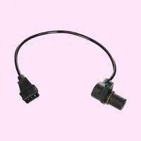
The camshaft position sensor is usually located on the engine’s cylinder head. However, the sensor location can vary from model to brand.
As the name suggests, 3 wire cam sensor connector has 3 wires, ground, live(power), and a signal wire. We have to test the voltage and resistance of the cam sensor wires to evaluate the sensor’s health.
We can identify signal and live wires of the connector by testing voltage from ground to each wire, such as ground to power and ground to signal wires.
Set your multimeter to DC volts to identify wires in the cam sensor connector (as the battery supplies direct current).
Connect the black multimeter probe to the ground wire at the center of the connector and the red probes to the rest of the wires.
The wire which displays around 12 volts is the power wire, and the one that shows around 5 volts is the signal wire.
- The power or live wire carries current through the battery and should have a voltage equal to the battery, such as 12 volts.
- The Signal wire shares information with ECU and should have around 4.8-5 volts.
- The ground wire completes the circuit and goes to the negative battery terminal.
Step 2: Test the voltage of the cam sensor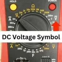
The cam sensor should be connected to your car battery or active power source to test voltage.
As mentioned above, set your multimeter to DC voltage. Connect the black multimeter probe to the ground wire (at the center of the connector) and the red probe to the other wires.
The live wire of the cam sensor connector should have around 12 volts (equal to battery voltage), and the power wire should have around 5V.
After identifying the wires in the cam sensor connector, verify if their voltage is in the ideal range, such as 12 V (maximum) for the power wire and 5 volts for the signal wire. If the voltage of the wires is below the ideal range, then your can sensor connector’s wires are damaged.
After testing the voltage, attach the black probes to the ground wire terminal and the red probe to the signal wire (that has a 5 V)terminal. Take a metal and pass it through the sensor, and you’ll see the multimeter reading drop to 0 V.
When you remove the metal from the sensor, the voltage reading returns to normal. It indicates that your sensor is sensing the movement correctly.
Also, check the condition of the ground wire of the cam sensor connector by attaching the black probe to the ground wire and the red probe to the positive battery terminal.
If the ground wire is fine, the multimeter should display the exact voltage of your battery. For example, if your battery is charged up to 12.6 volts, then a fine ground wire should have the same voltage as the battery.
If the reading is below the battery’s voltage, the ground wire is damaged and leaking current.
Step 3: Test the resistance of the cam sensor
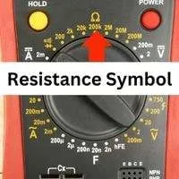
To calculate the resistance of the cam sensor, set your multimeter to ohms(Ω) (sign). Select a range such as 1000 ohm or above.
Connect multimeter probes to the terminals of the cam sensor connector. You can connect probes in any sequence as resistance is non-directional.
Ideally, the ohm reading on the camshaft position sensor should be below 1000 ohms. Check out the resistance reading on the multimeter and compare it with the recommended range of your cam sensor model.
Consult the manufacturer manual to verify the voltage and resistance ranges.
Signs of the Bad Crankshaft Sensor
Symptoms of the bad sensor are given here:
The engine icon which is on your dashboard indicates that there is a problem with your engine. If this light turns on it, there is a problem with the component of the engine.
When you monitor that gear is stuck in the case when trying to transmit one into another, it shows that the crankshaft sensor is going through the problem.
The fuel ignition gets damaged when the fuel injection timing and volume are not too good.
The bad crankshaft leads to the faulty working of the fuel injection.
Conclusion
A 3-wire camshaft position sensor can be tested by measuring voltage and resistance with a multimeter. The ideal voltage for the power wire is 12 V, and the signal is 5 V. Also, inspect any damage to connector wires. Resistance in connector terminals should be below 1000 ohms.
If you found this post helpful, share it with others and give your opinions in the comment section.
Related Guides: