There can be several symptoms of a faulty or dead hall effect sensor, including loss of power, trouble starting the car, stalling, and loud noises such as a blocked engine. That’s why it’s necessary to timely test a hall effect sensor with a multimeter or apply any other technique you know.
This article will describe how to test a Hall Effect sensor with a multimeter.
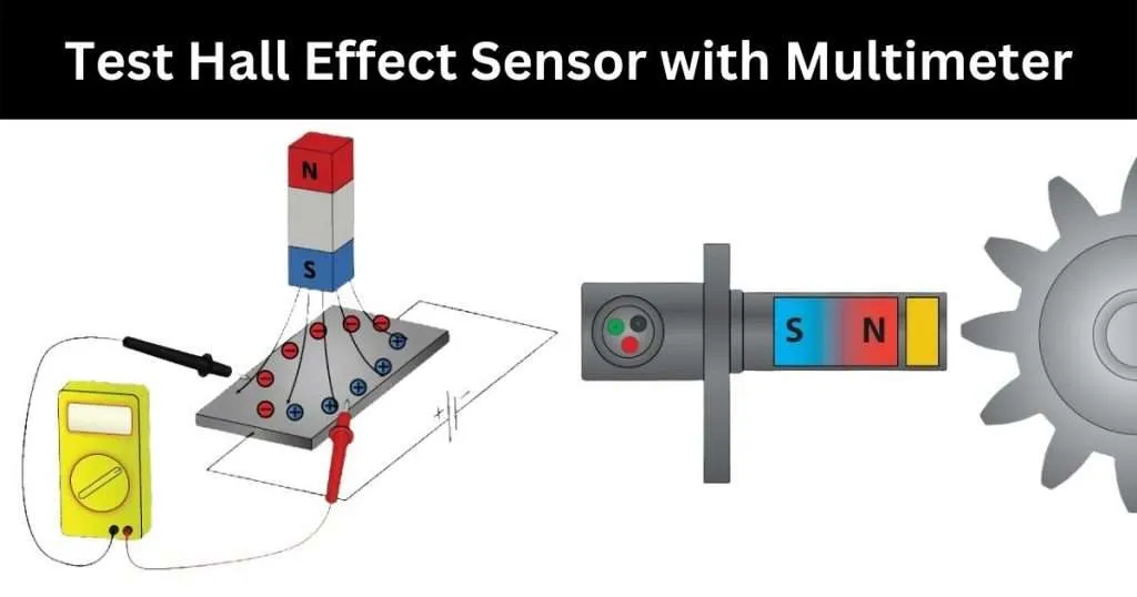
How to test a hall effect sensor with a multimeter
Steps to test a hall effect sensor with a multimeter:
- Set your multimeter to DC voltage.
- Connect the red probe to the sensor’s red wire and the black probe to a ground point.
- Your multimeter must display around 13 volts.
- When the other magnet gets closer to the sensor, voltage drops on the multimeter.
- Continue by examining the output of other wires.
Follow the detailed step-by-step guide below:
Step 1: First, disconnect the motor
Start by removing the bottom cover below the scooter to reach the controller. Remove the connector for the hall sensors after unplugging the battery (the red circle on the image), your motor’s three phases (the yellow circles), and the battery (green).
The cable may then be extracted by taking off the red rubber cover on the scooter’s side. The entire test will be simpler as a result.
Step 2: Turn on the engine.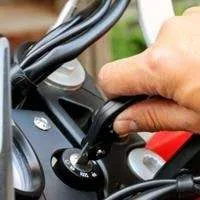
I won’t go into depth about this stage as many materials are accessible. But to reach the screws, you need to remove the reflective stickers on either side of the wheel. After that, take off the plastic covers and unbolt the fasteners on each side using a wrench.
In my instance, they used so much glue on the threads that I couldn’t spin the bolt without first using a heat gun to soften the situation somewhat.
If you must use this approach, don’t burn the cable; I created a little protective screen from a thin wooden board with a hole. The side panel must then be unscrewed and carefully pulled out.
Step 3: Inspect the motor
When your motor is opened, you can see the coils, the magnets, and some wires leading to a bit of PCB. We are primarily interested in this section. If you don’t have burned coils (copper wires that are black or charcoal-like), loose magnets, or any other mechanical problems, it is still worth inspecting.
You will have shorts if the coils are severely burnt, and it is doubtful that the motor can be fixed at this stage. Make that the inner section (the one with the coils) can be freely rotated; there may be some resistance owing to the magnets.
One wire for each hall sensor is coloured blue, green, and yellow. The connection that is inserted into the controller has the same colour scheme. This step will help us to test a hall effect sensor with a multimeter.
Step 4: Test sensor with a multimeter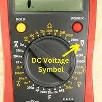
We’ll use a low DC voltage to power the board (typically 5V). The sensor’s red wire will receive the battery’s positive end.
The black wire will get the negative battery terminal(ground). The next step is to add a cable. That will serve as a probe for the various hall sensors.
We will use a multimeter to measure the voltage between the ground and the wire from one hall sensor.
For the remaining two hall sensors, we will follow the same steps.
- As the readings will be low, set your multimeter to the low DC voltage range, such as 10-20 V.
- A functional hall sensor will display the voltage on the first magnet and a very small voltage (zero or just a few millivolts) on the second magnet.
- You don’t have to test every magnet but keep turning the stator.
- You’ll find that the voltage readings on your multimeter display will alternate between being positive and being close to zero.
What occurs if the hall sensors malfunction?

Failure of the hall sensors indicates that vital data necessary for accurate synchronization of the motor’s power is missing from the controller, the board that powers and controls the motor.
Three wires supply electricity to the motor (phases). The three phases must be appropriately coordinated for the motor to operate without becoming stuck, losing power, or making a loud noise.
If you have a faulty hall sensor, moving it from one magnet to the next did not significantly alter the voltage on the multimeter.
This failure directly impacts the motor’s control. The controller will believe that the stator did not move despite the other. As a result, the engine will operate out of sync and rotate erratically.
How to Troubleshoot Hall Effect Sensor
Hall sensors are heat-sensitive, so the sensors might malfunction if your motor is exposed to high temperatures. The only immediate remedy is to swap out the defective parts for new ones.
The colored wires may be readily desoldered after separating the PCB housing the halls from the coils. Before continuing, please take a picture of your board; it could be helpful.
Remove the little insulation from the prior sensor, wrap some insulating thermal tubes over the pins, and resolder the old sensor. Verify the length and alignment that the hall sensor is correctly configured and that orientation is accurate.
This is a good test pattern for testing a hall effect sensor with a multimeter. But be cautious when removing the old component to avoid breaking the pins. Provide some means of eliminating leftover solder (copper braid or desoldering pump).
If I had to do it over, I would set the sensors within the stator’s little notch first, then install the board properly before soldering anything.
Conclusion
Hopefully, the question of how to use a multimeter to test a hall effect sensor is clear to you. High-speed operation, pre-programmable electrical outputs, and dependability are just a few advantages that Hall Effect sensors provide. Because it can function at a range of temperatures, users also adore it.
Hall sensors are frequently utilized in agricultural machinery, slitting and rewinding machines, process and packaging machines, automation equipment, marine handling equipment, and mobile vehicles.
Related Guide: