This is a step-by-step guide on testing a ballast with a multimeter. After the test, you can verify that the ballast is excellent and safe.
A fault in the lighting system of your room can create some trouble, especially at night time. Sometimes the bulb doesn’t glow even after replacing a new one. In this case, a faulty ballast could be a reason for no light.
A ballast in an electrical component that controls the whole lighting fixture (circuit). We have to test the ballast with a multimeter to know if it’s bad.
We’ll measure resistance in the ballast wires and terminals to identify a fault. If the ballast resistance range is not ideal, you may have to replace a new ballast for your lighting. A ballast usually lasts 15-20 years.
Let’s discover in detail:
What is a ballast?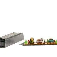
A ballast controls the voltage supply to a lighting fixture and prevents the circuit from loading and damaging your appliances. A ballast provides the voltage required to light a bulb and controls the supply to prevent the light from overcurrent.
Ballast consists of copper coils that engage a lot of current to pass through them, allowing a controlled amount of current to power the light bulb or tube.
There are two types of ballast, electronic ballast and magnetic ballast. Magnetic ballast comprises coils that control the voltage and allow a small amount of current to pass to the light. A magnetic ballast works at a 60 Hz frequency.
An electronic ballast doesn’t have coils and consists of rectifiers, resistors, EMI filters, and other electric components. An electronic ballast works at 20,000 Hz frequency; that’s why you don’t listen to any buzzing/arcing noise in an electronic ballast.
A ballast is a type of resistor placed in series with the load (light bulb) that limits the amount of current passing through a circuit.
A ballast performs two essential functions:
When a user turns on the light button, the ballast supplies the main power supply to the lighting circuit, including the bulb. An amount of voltage passes through the ballast coils that push through both the bulb’s electrodes and make it to light.
Secondly, a ballast controls the amount of current passing through the circuit and the light. Without a ballast, your lighting fixture will receive high voltage through the main outlet supply, causing overheating, and the light may blast, and its life span may reduce.
Ina ballast resistance increases with the increase of current, and it decreases with the decrease of current.
How to tell if a fluorescent bulb or ballast is bad?
If a fluorescent ballast goes bad:
- A faulty ballast could be the reason for flickering lights.
- A light bulb outputs low light.
- A bulb may flicker at takes time to glow.
- The bulb will not light up well, even after replacing a new one.
- The ballast may notice the passing current(sparking sound).
- At different stages, a light has different output levels (light). You may see the dark spot at the end of the bulb and the tube light.
How to test a ballast with a multimeter?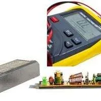
- To test a fluorescent light ballast, turn off the power supply.
- Set your multimeter to ohms at the highest range.
- Connect one probe to the white wire and the other probe to the rest of the wires(blue, yellow, red).
- However, some ballast can only have red, blue, and white wires, and you have to test resistance in the white and the rest of the wires.
- If your ballast is good, the multimeter will show OL or quite high resistance in the white and the other wires in the ballast.
- Low resistance in the wiring means the circuit is damaged, and the current leaks.
- There are also some older ballast versions with 2 or 4-round terminals. Check resistance in the row terminal. The older ballast has little resistance in ideal conditions.
Follow the step-by-step guide below:
Step1: Disconnect the ballast from the circuit
To test fluorescent light ballast, the first step is to turn off the power supply. We have to test resistance in the ballast wires, and direct contact with the live circuit can cause electrocution.
Unscrew the ballast cover to see the wiring terminals. The ballast cover may be hooked up with bolts.
After unscrewing the ballast cover, inspect the coils and wiring for damage. Overheating may cause the wiring to melt, and you may see dark burn signs and liquid in the ballast coils.
Step2: Multimeter Settings
To evaluate a ballast, we’ll measure resistance in the ballast wiring and evaluate if the circuit has an ideal resistance range.
Insert the red multimeter probe in the VmAΩ port and the black probe in the COM port
Set your multimeter to ohms(). Select a higher resistance range(megaohms).
Step3: Multimeter connection to the ballast
Connect on multimeter probe to the white wire and the red probe to all other wires.
You can attach multimeter probes in any direction because resistance is non-directional.
Step4: Evaluate Results from Multimeter Readings
In an electronic ballast, the multimeter should read OL (open loop) between the white wire(neutral) and the rest of the wires. There should be no continuity in the white wire with the others.
If the multimeter reads high resistance in the white and the other wires, then the ballast circuit is also considered fine.
However, if there is low resistance(better continuity) in the white (neutral) and any of the rest of the wires, then the ballast is faulty, as an ideal ballast should have very high resistance in the white and the rest of the wires.
However, a magnetic ballast can have different resistance ranges(ideal). These ballast models can have 2 or 4 round terminals. Set your multimeter to resistance and connect both probes to the two round terminals.
If the ballast is fine, your multimeter should read very low resistance and very high resistance or OL reading if the ballast is bad.
How to test a fluorescent tube with a multimeter?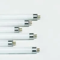
A fluorescent tube has two terminals at both metal caps(at both ends).To test a fluorescent tube, set your multimeter to ohms. Connect your multimeter probes to both terminals(pins) on each tube light cap(metal end). Check both metal caps of the tube light with a multimeter.
Tube light is fine if the terminals at both metal caps have low resistance, such as below 30 ohms.
While if any cap has infinite resistance, your multimeter reads OL(open loop), the fluorescent tube is faulty because the terminals don’t have continuity.
Conclusion
To have maximum output from your lighting system, ensure that your ballast is in good condition. A faulty ballast will trouble the whole circuit and appliances(lights) connected to it.
To ensure your ballast health, test resistance in the ballast. Compare the resistance values with the ideal range of your specific ballast model. However, you can generally compare the multimeter readings with the ideal resistance range in a magnetic and electronic ballast.
Follow the complete guide to test a fluorescent ballast using a multimeter.
If you still have queries, ask us in the comment below.
Related Guides?