Are you interested in knowing “how to test a stator with a multimeter?” Whenever your vehicle cannot start, there is a weak ignition, or the battery is not charging, possibly due to a faulty stator.
A faulty stator will not produce enough current, or the current is not reaching the battery or ignition box due to damaged wiring or a short circuit. You have to inspect the stator and wiring to figure out the problem.
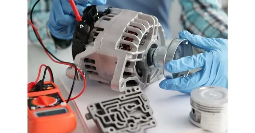
If the stator seems to be fine visually, you need to execute some tests on the stator with a multimeter. For this purpose, you should know how to test a stator with a multimeter.
In this post, we’ll discuss testing a stator using a multimeter to determine any fault causing poor performance in your ATV, scooter, or 3-phase engine. But before testing, you must know what a stator is and how it works.
What is a Stator?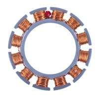
A stator is the stationary or fixed component of an electric motor or generator that lies inside the engine case, and a rotor spins inside it.
The stator consists of three parts. An outer frame protects the stator core and the winding. Stator winding is attached to the punching of the stator core.
3-phase power is supplied to the stator winding so that a rotating magnetic field is produced with the help of a rotor magnet, and the stator core carries this magnetic field. A stator winding is made powerful to carry heavy current, and insulation is made outside to prevent current flow.
What does a stator do?
When current is supplied to the stator winding, an electromagnetic field is produced due to the continuously moving magnet of the rotor part.
A constantly changing magnetic field creates an electromagnetic force (EMF) due to the phenomena of electromagnetic induction (varying magnetic field) in the current-carrying conductor. The EMF or AC voltage is converted to DC and is utilized in the motor.
The general working of all stators is the same. The purpose of installation may vary from motors to generators and Vehicles. In motorcycles and vehicles, the current produced in the stator charges the battery and generates power to fire the spark plug to aid ignition.
How to Test a Stator with a Multimeter?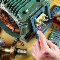
This lesson will work if you own a motorcycle, ATV, or scooter. Grab your multimeter and follow the guide.
-
Testing a Stator Out of Engine
This test is carried out while the stator is out of the engine and all wirings are dispatched.
We’ll perform several tests to determine any fault in the output, ignition wires, and pick-up coil.
Short circuit Test
- Grab the yellow wires grouped separately. The three yellow output wires charge the battery; that’s why it’s said to be a 3 phase stator. A low-powered engine contains 2 phase stator.
- Don’t use green and blue wire, as they are for ignition. Also, the green and yellow wires should not connect to each other.
- To check if the current is short-circuited into the stator or bike body, connect one probe to yellow wires and the other to the stator body.
- If there is no continuity, you will get OL or 1 reading on the multimeter, indicating an open loop or no current flow.
- However, if the stator is short-circuited, the multimeter will show you 0 in the continuity test or the resistance in the Ohm mode, which means that the current is passing somewhere.
This is how you test a short circuit in a stator. And also test for any short circuit between ignition and output wires.
- Check all the yellow (output-battery) wires with the green and blue (ignition) wires to inspect short circuits.
- Your multimeter must read 1 or OL while testing the blue and green with yellows.
- It indicates no connection between the ignition (blue, green) and the charging wires (yellow).
- If they are connecting to each other, it may cause the stator to burn due to a short circuit.
Resistance Test in output wires
After you have ensured there is no short circuit, check the output wires to see if they have the same resistance.
- For this purpose, insert black and red probes in all the yellow wires.
- You will get three readings by inserting probes in the 1st and 2nd wire, the 2nd and 3rd, and the 3rd and 1st.
- The purpose is to check the same resistance in all the wires, and all three phases should have the same reading.
- Also, test both ignition wires, and the resistance must be in the range of that particular stator.
Pick up coil test
A Pick-up coil is used in the ignition system of vehicles. It generates a voltage pulse carried as RPM to the ignition module.
You must also test the pickup coil to see if its reading is in range.
- Place the black probe in the blue wire plug and the red probe in the ground metal of the pickup coil.
- The measured reading of the pickup coil, also known as SPEC, must be in the range of that specific stator used in your motorcycle.
- You can check that range in the manual or find it online.
-
Static Stator Test
A static stator test is done when your vehicle is turned off. When you face a problem with the battery charging or the ignition, you can do this test while the stator is on the bike.
Pick up your multimeter and follow these steps.
Resistance Test
- Whether your bike has two or three-phase stators, attach the probes of the multimeter to phase 1 and phase 2, selecting the ohm setting on the multimeter.
- In a three-phase stator test, connect the probe with 2 phases and get three readings with two different wires every time.
- For a perfectly working stator, it’s necessary to measure the same resistance through all output wires, whatever the reading is. It means that all the cables are working with the same resistance. Otherwise, your stator is having issues while charging the batteries.
- Also, note that a perfectly working output wire should have a .3 to .5 ohm reading; otherwise, it could be a faulty stator.
Voltage and Continuity Test
- While measuring AC voltage on a switched-off engine, the multimeter will show 0V on all phases of output wires. It’s because no power is generated in the stator at that time. This is how to test a stator output.
- To check continuity in output wires, test all phases with each other. If the multimeter shows 1 or OL, there is no continuity, and any of the stator components are not working, causing a broken circuit path.
When a vehicle is off, it’s inefficient for a complete voltage test as the engine is off, and you can’t test the change in voltage. For this objective, we follow a dynamic stator test.
-
Dynamic Stator Test
The dynamic stator test is carried out when your vehicle is switched on. In a dynamic stator test, the output wires’ voltage is compared to ensure the engine goes well with the battery.
Voltage test when the vehicle is switched on
- Before you have switched on the bike, the AC voltage reading in all phases must be zero. There is no current due to the vehicle being powered off.
- Now turn on the switch, and you must see the voltage change. Its limit must be in the limit of your stators model.
- Increase the throttle or rev up the engine so that the stator increases the amount of voltage in the output wires.
- Readings on all three wire combinations must return the same output, and voltage should increase with the increasing RPM.
- It could be a fault if you find a significant difference in the reading. Also, no voltage means a failed stator.
Ignition Test
- To check the ignition and spark plug of bikes with a multimeter, put one probe to the ground wire from the stator and the other probe to the wire going to the ignition box.
- So if there is a fault, your multimeter will show 1 or relatively high resistance, meaning there is faulty wiring or stator.
By this test, you can check if the stator is giving enough power to the ignition box or if there is a fault in the ignition wiring or the stator itself.
FAQs
What is a bad stator symbol in a motorcycle?
A bad stator on a motorcycle will affect the ignition, produce a weak electric spark, and the bike may not start. The battery will not fully charge, causing dim lights and poor functioning of accessories that depend on the battery.
How to test a stator on a Kawasaki engine?
A Kawasaki engine is built of a 3-phase stator. If the battery is not charging well, you must check all phases with each other for a voltage and continuity test.
Attach probes to a to b, b to c, and c to a. Multimeter should read 12–25VAC output if the stator works perfectly in all phases, and voltage should increase with RPM.
A significant voltage difference in any phase indicates a poor connection or faulty stator, leading to battery charging issues.
You can follow the detailed guide above to do a spark plug or ignition test.
How to test a stator without a multimeter?
Without a multimeter, you can inspect only significant defects in a stator. If the stator or wiring is burnt, you can figure it out visually. In such cases, the multimeter has no use.
However, for a detailed complication assessment, you need a multimeter to check voltage, resistance, continuity, and a short circuit.
Conclusion
In this post, we discussed how to test a stator with a multimeter to examine any possible fault. Taking the stator out of the engine every time is not suitable, but it gives you the most reliable results. You can do it yourself if you have a multimeter and understand how to operate with engine wiring.
Using a multimeter, you can perform resistance, continuity, voltage, and pickup coil tests to know which stator component is not working efficiently. Hopefully, this guide will help you configure your bike stator errors.
Related Guides: