Worn-out terminals or short circuits in the ignition key switch can make your car not start, go off while running, or starts when the key is off. It’s easy to test an ignition switch with a multimeter than with other tools.
An ignition switch can have different terminals, such as boats and tractors having six terminals and cars having 4-5. You must know the key switch terminals (where wires are connected).
We’ll measure the voltage in the ignition switch terminals in different key positions to check the voltage supply. We can determine whether the terminal and switch body have quality connections by checking connectivity in terminals.
Let’s discover the basics in detail:
Table of Contents
ToggleHow to test the ignition switch with a multimeter
A 5-terminal ignition or key switch has five terminals G(ground), B(battery), L(light), M(magneto), and S(Solenoid).
To test the voltage.
- Set your multimeter to DC voltage sign at 20V range.
- Connect the black probe to a ground point and the red probe to B(battery) terminal on the ignition switch.
- If you are testing a car ignition switch multimeter should read 12V(battery voltage).
Now set the multimeter to continuity:
- Test B and L terminal in the Run position.
- Now test B and S terminals in the Start position.
- At last, test the G terminal with M and L terminals in the Off position.
- The ignition switch is fine if your multimeter shows continuity or 0Ω resistance at these terminals.
Carefully read these terminals and their connection in their specific positions and test voltage and continuity.
Follow Step by step:
Step 1: Unscrew the ignition switch
Remove the bottom steering shroud; this process could differ in different vehicles.
Unscrew the switch and take the switch out along the wires
Locate the terminals at the backside of the ignition switch.
Step 2: Set your multimeter to DC Voltage
Set your multimeter to DC voltage, as a vehicle battery supplies DC voltage. Set a range above the battery’s voltage, such as 20V.
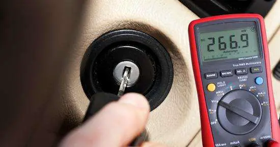
Step 3: Connect probes to ignition switch terminals
Connect the black multimeter probe to any ground connection. There are several ground points on your car, and you can take any metal body part as a ground point.
Connect the red probe to terminal B(battery ) at the backside of the ignition switch.
When the vehicle is off, your multimeter will show around zero voltage.
Now rotate the ignition switch in the RUN position, and the voltage reading on the multimeter will increase(12V).
Step 4: Check voltage and evaluate the ignition switch
- In the Run or Start key position, B(battery) terminal should have around 12V. If the key switch circuit is fine and gets enough voltage to perform essential functions.
A major decrease in the multimeter’s voltage reading indicates that the switch, wires, or battery are faulty. - Now place the black probe on a ground point in your car and the red probe on the L terminal and rotate the key in the RUN position, and the multimeter should read above 12V.
- Same as above, now test the S terminal with a ground point in the key START position, and the multimeter will read around 12V.
Test continuity in ignition switch terminals
To test an ignition or key switch, we’ll check continuity in the switch terminal in the Start Run and Off position(key rotation).
The continuity test checks whether a circuit has a complete path(loop) for current or not. The multimeter will beep or show the circuit’s resistance if the tested circuit has a continuous path(complete). While if a tested circuit has a non-continuous path, the multimeter will show OL with no beep.
A 5-terminal ignition or key switch has 5 terminals G(ground), B(battery), L(light), M(magneto), and S(Solenoid)
- First, we’ll test continuity in the B(Battery) and L(Light) terminals of the ignition switch in the Run position. Connect one probe to the B terminal and the other probe to the L terminal. The multimeter should read around 0 ohms(continuity)
- We’ll test the battery (B) terminal with the solenoid terminal(S) at the START position. Connect your multimeter probes to both terminals(B and S) and rotate the key in the START position. There also multimeter should read around 0 ohms.
- At last, check the continuity in G(ground) and M(magneto) terminals in the off position, and the multimeter should read the continuity in terminals.
Signs of Faulty ignition switch terminal:
Sometimes, a multimeter shows changing continuity (ohms) when a terminal gets loose. In this condition, you’ll have to tighten the screw of the ignition key terminals.
Test short in the Ignition Switch terminals
- To test a short circuit in the ground terminal of the ignition switch, connect one probe to the ground terminal and other probes to the rest of the terminal one by one. If the ground terminal is fine, it should not have continuity with any other terminal if the multimeter shows continuity between the ground and other terminals. It means that the ground terminal is short-circuited.
- Now check the continuity of the Ground terminal with the ignition switch base. Content one probe to the ground and the other to the metal base of the ignition switch.
The ground terminal should have continuity with the key switch base. The multimeter will display continuity as a beep or low resistance value.
This way, check each terminal with others, look for a faulty one, and screw it tightly.
Frequently Asked Questions
-
How to test the ignition switch on a tractor?
Like other vehicles, tractors can have differences in the number of terminals in the ignition switch.
Usually, when the switch is off, the ground(G) and magneto(M) terminals are in contact, and your vehicle goes off. Test continuity between your tractor key switch’s G and M terminals should have around 0 ohms.
While the ignition key is in the RUN position, battery terminals (B) and L connect. So, we’ll check for continuity between B and L terminals, and they should have 0 ohms.
At last, in the Start position, when we rotate the key, Battery(B) and Solenoid(S) get into contact, and they should have maximum excellent continuity(0 ohms).
As we leave the key, it returns to the Run position, and L and B(battery) terminals get connected.
-
How to test a boat ignition switch with a multimeter?
To test the boat ignition switch:
- Unscrew the ignition switch box and take the switch out with wires. Set your multimeter to DC voltage at 20V range. Attach the black multimeter probe to a ground point (any metal body part in the engine)
- Connect the red probe to the B terminal. This terminal should read around the battery’s voltage (14.2 to 14.4V) in the Run and Start positions.
- Now, connect the red probe to the I(ignition) terminal and rotate the key in the Run position; the multimeter shroud reads near the battery’s voltage.
- Now connect the red probe to the S(Solenoid/Start) and rotate the key in the Start position. The multimeter should read above 14V.
- If there is low voltage in any terminal, unplug all wires and test the continuity of the terminals in the off, run, and start positions.
-
How to check the ignition switch fuse?
The ignition switches fuse supplies and controls the power of the ignition switch. Usually, there are two locations for the fuses. One is near the passenger seat (near the dashboard or steering), and the other is in the bonnet.
To test the ignition fuse, locate it in the relay panel and remove it. Now set your multimeter to continuity and connect both probes (black & red) to both fuse terminals.
A fine fuse should have minimum resistance, which means excellent continuity. The tested fuse is bad if the multimeter reads OL or has high resistance.
-
How to start a car with a bad ignition switch?
Open your car’s bonnet and locate the ignition coils. Connect the battery’s positive terminal with the positive terminal of ignition coils with a jumper wire(cable). In this way, the battery will directly supply voltage to the ignition coil and then to the dashboard for ignition.
Conclusion
We have explained each step to teach you how an ignition switch works and test it with a digital multimeter.
If you have any related queries, feel free to comment.
Related Guide: