This article describes how to use a clamp meter to measure DC current, and about clamp meter functions, parts, and uses.
Tools are used for detecting dc current with the help of sensors due to the uneasy method in electromagnetic induction for dc clamp meters. Element keeps across transformer jaws for getting the measurement of dc current. When the flow of magnetic flux is proportional to DC primary currents in the transformer jaws, the hall element shows the magnetic flux and gives output voltage.
A semiconductor generates a voltage proportional to the output of the bias current and magnetic field on the output terminal when the bias current is charged to the input terminal.
Clamp meters are mostly used for electrical applications measurements such as voltage, resistance, capacitance, and continuity.
Tong tester is the other name for clamp meter, which is helpful for live conductor measurement. Low accuracy is considerable for clamp meters, which is a disadvantage of this testing equipment.
How to use a clamp meter to measure DC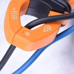
Here is a quick guide to understanding the basic steps:
Quick steps:
- Place the clamp meter in the circuit
- Set the clamp meter to measure the DC.
- Place the clamp meter’s jaws around the circuit’s first wire.
- Take the readings of the DC.
- Place the clamp meter’s jaws around the circuit’s second wire.
- Note the readings of the DC current
- Repeat the method for all the wires in the circuit.
- Compare the value of the DC current of all the wires.
Below we have explained a detailed step-by-step guide on How to use a clamp meter to measure DC current:
Now we will briefly explain each step of using a clamp meter to measure a DC current so that the testing procedure will become clearer to you, and you can easily use the clamp meter after taking the full view of this explanation.
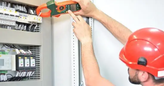
Step 1: Place the clamp meter in the circuit:
To measure the DC current of the wires of a specific circuit, you have to place the clamp meter in the circuit so that it will be able to measure the DC current of the wires of that circuit. So place the clamp meter in the circuit carefully.
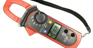
Step 2: Set the clamp meter to measure DC current:
To measure the DC current from the clamp meter, you have to set the clamp meter to measure the DC current. You must turn the clamp meter’s dial towards the DC option. Now the clamp meter is ready to measure the DC current.
Step 3: Place the jaws of the clamp meter around the first wire of the circuit:
Clamp meters have rounded jaws where you grab the circuit’s wire to take the DC current readings. So, starting the procedure, you must place the clamp meter’s Jaws around the circuit’s first wire.
Step 4: Take the readings of the DC current:
When you place the clamp meter’s jaws around the first wire of your specific circuit, you will get the reading of the DC current of that wire. For the readings, you must see the clamp meter’s display screen. Note down the DC current readings of the circuit’s first fire.
Step 5: Place the jaws of the clamp meter around the second wire of the circuit:
After measuring the DC current value of the first wire of the circuit now have to measure the DC current value of the second wire of the same circuit. For this, you have to place the clamp meter’s Jaws around the circuit’s second wire as you do for measuring the DC current of the first wire.
Step6: Note the readings of the DC current:
After placing the jaws around the second wire, you will get the value of the DC current on the display screen of the clamp meter. From here, you have to note down the DC current value of the second wire.
Step 7: Repeat the method for all the wires in the circuit:
Repeat this method of measuring DC current for all the wires of the circuit you are using in this testing procedure. Measure the DC current value of all the wires one by one and note down the readings.
Step 8: Compare the values of the DC current of all the wires:
After measuring the DC current value of all the wires of one circuit, you will get the specific readings at the end. Now you have to compare the values of the DC current of all these wires.
The wire with the largest DC current value is the one that uses most of the current in the circuit, and you can call this wire a load on the circuit.
How to use a clamp meter?
We have explained the basic functions, parts, and operating systems below if you are using a clamp meter for the first time. Let’s explore this in detail:
Functions of clamps meters
The function of clamps meters on the basic principles of current transformer (CT) used to carry magnetic flux, which is the output of flowing current through a conductor.
The primary current is the result of current flowing through a conductor by electromagnetic induction of the secondary side of the transformer, which is attached to the measuring circuit of the instrument.
Clamp Meter Measurements
The clamp design is for current measurement only; clamp meters mostly receive input from test leads or investigation, which increases measurement types by which competent and making versatile this instrument is.
- DC current:
Ampere is the measurement of current that is a flow of an electric charge and is also an essential clamp meter measurement. Current produces heat, and magnetic fields are used for motors, inductors, and generators.
- DC voltage:
Volts are the measurement of voltage, the difference in electrical power of a unit charge transported between two points or others; electrical energy is handed over if electrons are transmitted through a circuit in huge quantity.
- Resistance:
An ohm is a measurement unit of resistance. It resists the passing of an electrical current through a conductor. Resistance is identified by the conductor’s material and shape.
- Continuity:
The resistance test differentiates between an open and closed circuit in the quick “pass/fail .”Continuity tests deliver a tone when disconnecting a closed circuit and observing the meter for the required test performance.
- Capacitance:
Farad is the measurement unit of capacitance, the ability to store an electrical charge in an object. Capacitance exhibits electrically charged in any object.
- Frequency:
The frequency measurement unit is hertz; alternating current by oscillations occurs in an electric power grid.
- Power Factor:
The ratio between the real powers flowing to the load to apparent power in the circuit. Power factor is a modern technology for measurement in an electrical system; a low power factor load draws more current than a high power factor load for the same power transferred.
- Temperature:
Clamp meters take input data from temperature elements or thermocouples to detect the contact temperature measurement.
Parts of the Clamp meter
- Transformer clamps (Jaws)
The sensor of transformer clamps senses the magnetic field of flowing current through the conductor.
- Clamp opening trigger
The function of the clamp’s opening trigger is to open/ close.
- Power switch
Meter can be powered on/off by this switch.
Backlight button
- The backlight button increases or decreases the screen display light for night or dark mode for easy reading values.
- Hold button
This button holds the value of the last reading on the LCD screen.
- Negative/ ground input terminal
The function of this terminal is to connect the meter cable’s negative/ ground jack.
- Positive input terminal
The usage of this terminal is to connect the meter cable’s positive jack.
- LCD
It shows the values of measurement.
- Functional rotary switch
The purpose of the switch is to select or change the type of range of current which is to be measured.
Types of clamps meter
Clamp meters are categorized into two types that quickly purchase in the market depending on the measurement of current nature.
- Current transformer clamps meter- used to measure alternating current only.
- Hall Effect clamps meter – used for measuring both direct current (DC) and alternative current (AC).
Operating principle of current transformer clamp meter
There are two clamps made from ferrite iron in a current transformer. Copper coil independently wrapped around these clamps. Both of them produce magnetic cores together to get the measurement. The principle of electromagnetic informs about the flowing of current through conducting materials, which is the reason for the magnetic flux generation.
Consideration, the conductors by which current passes through are the transformer’s initial part. Due to the movement of currents, magnetic fields produce in it. When clamps meter arms are placed for getting measurement, it works as the transformer’s secondary winding.
The clamps meter’s iron core arm focuses on the primary winding’s magnetic field, although the current is proportional to the generation of direct current by electromagnetic induction.
The clamps meter’s arm is connected to a measurement circuitry for getting finally current reading. Magnetic field measured in magnetic flux. Its symbol is (ⱷ) phi, which is a Greek letter.
Operating principle of Hall Effect clamp meter
The Hall Effect clamps meter is similar to the current transformer clamps meter. It consists of two clamps which are made from ferrite iron. Although the Hall clamp meter is not similar, the current transformer clamp meter is wrapped with copper wire.
When the conductor close around the conductor magnetic field induces current flowing during the conductor in the gap.
The Hall Effect sensor, a small semiconductor component inside the gap, is not visible due to the plastic molding cover. It can vary its output voltage on the magnetic field variation by a special transducer due to current flow in the conductor.
The voltage produced by the Hall Effect sensor that moved for amplification and graph showing the current flow through a conductor. As core can concentrate DC magnetic field that can measure DC current as a Hall Effect clamp meter.
The clamps meters must be balanced to zero to avoid errors because of the earth’s magnetic field or another source of magnetic fields in an open atmosphere.
Frequently asked questions
How does a clamps meter measure DC current?
Clamps meters measure DC current with a voltage output clamp by dialing mVdc for dc current. Insert the plug for the black test into the COM jack.
Can you measure DC voltage with a clamp meter?
A clamp meter can measure dc voltage because it is a standard function.
What is the difference between a clamp meter and a multimeter?
A clamp meter is a primary tool for measuring current flow. At the same time, a multimeter has functions to measure voltage, resistance, and continuity, and in rare times, it measures low current.
The main difference between clamp meter and multimeters are clamp meter measure high current while multimeters can measure with higher accuracy and achieve better resolution.
Conclusion
The clamp’s plugs interested into the meter, and the meter must be fixed at zero to avoid errors. The clamp meter should have to offset before the ZERO buttons are used. Then clamp meter is placed around the wire, and measure the flow of current will be shown as volts on the millimeter; conversion must be applied for the factor specified on the clamp.
Related Guides: