A relay is an essential electrical component acting as a switch to turn a device or car function. When the relay is bad, you can’t turn on an accessory such as a headlight or AC. To know if a relay is bad, we’ll test a relay corresponding to the faulty component with a multimeter. This article will guide you on how to test a relay using a multimeter.
First, understand:
What is a relay, and how does it works?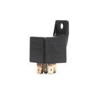
A relay is an electrical component installed in vehicles, home appliances, and circuits, used as a switch(power barrier). It input’s low voltage through the coil terminals to switch the circuit On or Off.
They are installed between the ECU and a device, such as a headlight, to work as an on-and-off switch. When we use a function such as a turn on the headlight, the air conditioner ECU sends signals to the corresponding relay. A little voltage enters the coil(wire winding)
A relay is designed such that a small amount of current(ECU signals) acts as a barrier(switch) to the battery’s voltage supply. When your start a function in your car, that little voltage turn’s the switch(armature/pin) from the off to the on position. So the circuit completes, and the full voltage supply reaches the accessories for functioning, such as the air conditioner, headlight, etc.
There are two terminals used to switch on and off a circuit. An armature is joined to the COM terminal that connects to the NC terminal(normally closed) when there is no power in the circuit. When we turn on an accessory, voltage passes through the relay and turns the armature to the NO(usually on) position, which allows full voltage to pass through the circuit(such as the headlight).
When you turn off the function, the voltage supply stops, and the pin moves from the NO(normally open) to NC(normally closed) terminal making the circuit open.
Modern cars have around 20 relays to control various functions, such as speakers and headlights.
Relay terminals are marked with numbering such as a 5-pin relay in the car is marked 30, 85, 86, 87, 87a. You should check your relay model diagram to identify coil, NC, NO, and COM terminals.
When we turn on a function in the car, such as the headlight, ECU passes signals to the relay to consume a small amount of voltage and turn the switch circuit on. Current travel through the coil windings and turns the armature from NC(normally closed) to NO(normally open terminal).
Due to the voltage supply, the armature will move from NC(normally closed) terminal to the NO(normally open) terminal, completing the circuit and allowing the maximum voltage supply(12V) to pass through the entire circuit to glow the headlight.
In the same way, when we turn off the headlight, the armature switch will move from NO to NC terminal, the circuit will turn off, and there will be no power to the headlights.
There are also 2 terminals on the relay, known as input or coil terminals, that supply power to the relay coil to turn on or off the circuit by turning the armature.
How to test a relay with a multimeter?
To test if a relay is working.
- Set your multimeter to resistance(ohm) at 200Ω.
- Identify terminals with the relay diagram.
- First, connect both probes to the relay’s coil terminals (input). The coil terminal should have a resistance between 40-200Ω.
- Now connect both probes to the COM(standard) and NC(normally closed) terminals. COM and NC terminals should have continuity when the circuit has no power.
Understand Wiring of the Relay:
Connect the coil terminals(input) to the battery and check continuity in the COM and NO(normally open) terminals. When power is on, COM and NO terminals should have continuity.
So we’ll check continuity in the COM terminal with the NC terminal while the circuit is closed(without a power supply). Then we’ll connect the relay to a power source and check continuity in the COM and NO(normally open) terminals.
We’ll test resistance in the relay’s coil terminals(input).
Relays usually have 3-6 relay pins or terminals, and you have to locate the terminals according to the diagram.
If you are testing a car relay, you should locate the relay panel(box) under the steering wheel or under the bonnet near the engine.
Set multimeter and connect to relay terminals:
Set your multimeter to resistance set at 200 ohms range.
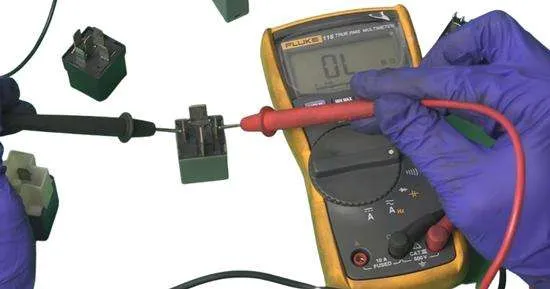
Relay models can have different pins, so locate your relay pins with diagrams online. Connect both probes to the coil terminals(input) of the relay.
You can connect the probe in any direction on the relay coil terminals because resistance (continuity) doesn’t have a direction.
Check relay with multimeter reading:
If a relay is fine, the multimeter should read around 40Ω to 120Ω. However, resistance ranges can vary in different relay models. While the input coil terminal doesn’t have continuity, the multimeter will read(OL), which means that the relay coil(winding) is damaged.
Test Continuity in the Relay switch terminals:
COM and NC(normally closed) terminals have continuity when power is off. After the power is on, COM and NO(normally open) terminals are in contact.
Remove the relay from the circuit. Set your multimeter to continuity mode. Touch both probes to the COM and NC(normally closed) terminals. When there is no current multimeter should detect continuity in the COM and NC terminal. While if your multimeter reads OL, which means a broken circuit, the relay is faulty.
Now take a battery equal to the relays. Energize the relay by connecting both coil terminals to the battery terminals.
Adjust your multimeter to continuity and connect probes at the COM and NO(normally open terminal). If the coil and relay are fine, the multimeter should detect continuity in these terminals.
If there is no continuity, the relay is damaged.
How to test a relay circuit?
- Detach the relay from the circuit. Take a small piece of wire with both bare ends and insert them into the live and ground terminal of the relay circuit, for example, the fan relay.
- Wear gloves and remove the relay cover. Pressing the metal plates(terminals) will connect to each other, completing the circuit. Insert the relay in the circuit without cover and slightly press the metal plates. You’ll see the relay you’ve tested will make the component work, such as fan, ac, or headlight starts.
Frequently Asked Questions
How to test a relay without a multimeter?
To test a relay without a multimeter, attach the coil terminal in the relay to a battery. When the circuit is complete, the relay will make a clicking sound of the armature turning from Closed to Open.
If there is no sound, the relay could be faulty.
How to test a 4-pin relay with a multimeter
A 4-pin relay has 2 coil input terminals, a common terminal(COM), and an NO terminal(normally open). First, test resistance in the relay coil terminals. A good relay should have 40-200 ohms in the input(coil) terminals.
Now attach the relay(coil terminals) to a battery. Test continuity in the COM and NO(normally open) terminals after the battery is connected. A good relay should have continuity in COM and NO terminals.
If the multimeter reads OL(open loop), the relay circuit is open(broken).
How to test a relay with a test light?
Connect the alligator clip of the test light to your car’s negative battery terminal. Now insert the test light needle in the live terminal of the relay circuit. The test light should glow, indicating continuity.
Now connect the test light alligator clips to the positive battery terminal and insert the test needle in the ground terminal of the relay circuit. If the relay circuit is complete, the test light will glow.
How to test a 5-pin relay with a multimeter?
To test a 5-pin (12V) relay, test the resistance in the 30 and 86-pin. There should
be around 40-200 ohm resistance. Also, test continuity in pins 85, 87, and 87a.
Conclusion
You can test a relay quite quickly if you are a beginner. Wear gloves and handle the relay softly, as a hot can damage coil windings. Use your multimeter’s resistance and continuity settings to test the relay’s input and switch terminals.
Relays are available in 3-6 pins, so follow the circuit diagram of your relay model for testing.
Learn the complete step-by-step guide to understand how a relay works and test the relay with a multimeter.
Share your queries in the comments below.
Related Guides: