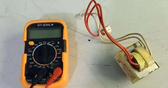
In this post, we’ll discuss how to test transformers with a multimeter. A transformer is an essential component of many devices used in your home, such as a refrigerator, inverters, and mobile chargers. A transformer lowers or magnifies the input voltage according to a device’s requirement.
A faulty transformer can overload your device and may burn your appliances. That’s why testing a transformer with a multimeter or tool is necessary.
What is a transformer, and how it works?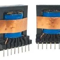
A transformer is an electrical device that converts the input supply to lower or higher voltage signals. A transformer has two loops wrapped around two iron cores and insulated from each other. The secondary coil converts the input voltage from the primary coil into the ideal voltage supply that the device uses.
When you connect a device to a power supply, current enters the primary coil and creates a magnetic field. The secondary coil feels this magnetic field in the primary coil. Due to electromagnetic induction, an electromagnetic field also develops in the secondary coil that drives current in the secondary coil.
The number of loops in the primary and secondary coils decides whether the transformer will be used to lower or expand the input voltage.
Suppose the primary coil has greater wiring loops than the secondary one. In that case, your transformer will convert high voltage to low voltage.
How to test a transformer with a multimeter?
- To test a transformer, we’ll measure voltage and resistance in the primary and secondary coils.
- To test a transformer, set your multimeter to AC voltage.
- Measure the voltage at the input and output terminals of the transformer.
- If you are testing a step-down transformer(high voltage to low), primary coil terminals should have a voltage equal to your home supply, such as 120-240.
- Output terminals (secondary coil) should have a low voltage.
- Consult the manufacturer manual’s recommended voltages of the transformer’s input and output terminals.
- Also, measure the resistance in the input and output terminals and compare them with the ideal range of your transformer model.
Let’s read in detail about how to test a transformer with a multimeter.
To test a transformer, we have to check the transformer’s resistance and input and output voltage.
If you are testing a step-down transformer, remember that the output voltage in a step-down transformer decreases as it functions to lower the voltage according to the usage of the device.
In a step-down transformer, the primary coil has higher resistance than the secondary coil due to the higher number of loops.
1. Test the input and output voltage of the transformer
First, we’ll test the voltage in the primary(input supply) and secondary coils(output).
For voltage testing, your transformer should be connected to an AC power supply, or you can test it while it’s installed in a device.
Set your multimeter to AC voltage to check the transformer’s input and output. A step-down transformer is used in appliances that work on alternating currents. Select a higher range, such as 600V, for testing the primary coil.
Supply power to the transformer circuit. Connect both probes to the input wires (terminals) of the transformer. These are the transformer’s primary coil terminals that input voltage from a power source such as an outlet.
In primary coil terminals(input), your multimeter should read around 120 – or 240 V. Multimeter reading depends on your home distribution, whether 120 or 240V.
Remember that if your multimeter reads quite low voltage in the primary coil terminals(input), the voltage supply is insufficient, or the primary coil wiring is faulty, supplying less voltage.
Now it’s time to test the voltage of the secondary coil in the transformer. As we know, the primary coil has 2 terminals, and the secondary coil can have a different number of terminals.
Connect both multimeter probes to the secondary coil terminals. In a step-down transformer, the secondary coil decreases the input from the primary coil to the ideal output voltage that a device requires to work.
For example, a step-down transformer in a mobile charger converts 220V into 5V, and different transformers used in different devices can have different output voltages.
So you have to compare the output voltage of the secondary coil with the ideal voltage range of your specific transformer.
2. Test continuity in the transformer
To test a step-down transformer with a multimeter, adjust your multimeter to resistance(ohm) at a higher range(above 2k) for the primary coil.
After setting your multimeter, connect both probes to the primary coil terminals.
The prime coil is expected to have around 1000 ohms(1k). If the primary coil terminals have too high, too low resistance or OL(open loop), then the primary coil in the transformer is faulty, and you need to replace your transformer.
Set your multimeter to the low resistance range to test the secondary coil. Connect both probes to the terminals in the secondary coil. The primary coil can have around 100-ohm resistance.
Remember that a coil with a greater number of loops has more resistance and one with fewer loops has low resistance.
In a step-down transformer, the primary coil has more loops than the secondary coil. The primary function of a step-down transformer is to convert high to low voltage. That’s why the secondary coil has fewer loops than the primary coil.
Ideally, you should compare the multimeter resistance reading of primary and secondary coils with the ideal ranges in the manufacturer’s manual.
The primary and secondary coils shouldn’t have any continuity because they are designed to be insulated from each other.
To test for short circuits in your transformer, connect multimeter probes to the primary and secondary terminals and check all terminals on both sides with each other. Your multimeter should read OL reading(open loop or infinite) between the primary and the secondary coils because there must be no continuity between them.
The transformer is shortcircuited if the multimeter reads resistance between the primary and secondary coil. The coils are shorted, and the current leaks between the primary and secondary coils.
Remember that if you can’t identify the primary and secondary coils in a step-down transformer, measure the resistance in the terminals on both sides. The terminals with higher resistance will be the primary coil, and the other with less resistance will be the secondary coil.
FAQs
How to test a transformer on a circuit board?
To test a transformer on a circuit board:
- Set your multimeter to AC voltage at a higher range.
- Turn on the power supply to the circuit.
- Measure voltage in the input and out terminals of the transformer(primary and secondary coil). Touch both multimeter probes to the input wires(primary coil) and then to the output wires. If you are testing a step-down transformer, the secondary coil(output) has a lower voltage than the primary coil(input). The primary coil should have around 120 or 240V(home supply).
How to test a 24V transformer with a multimeter?
A 24V transformer is designed to output 24 volts. We’ll test the output voltage of a 24-volt transformer to check if the output voltage is OK or not.
Ensure your transformer is connected to a circuit and the power supply is on. Set your multimeter to AC voltage and connect both probes to the output wires of the transformers. Your multimeter should read around 24V.
If the multimeter reading is too low, the coil windings or the circuit is damaged, and the current leaks.
Conclusion
There are two main components of a transformer(primary and secondary coils) that we’ve to examine to evaluate a transformer.
To check the transformer’s primary and secondary coil, measure voltage and resistance in the transformer’s input(primary) and output terminals(secondary coil). Compare the multimeter readings with the ideal ranges found in the manufacturer manual.
If you still have any queries, ask us in the comment below.
Related Guides: