We’ll check the motherboard by testing the Power Supply unit and the 24-pin connector that supplies power for the functioning of the motherboard and other components. With a multimeter, we’ll test the voltage and resistance of the wires in 24 pin connector.
A power supply unit can have 20 or 24 pins, with black, yellow, blue, red, and grey wires and each colored wire is assigned a function, such as the black wires for ground connection.
An ATX power supply unit(PSU) pins provide power to almost all the motherboard components and your PC. We’ll check the resistance and voltage of ATX harness connector wires.
Signs of a bad motherboard
A faulty motherboard can show these signs.
- Your PC may take a lot of time to start.
- The system works fast initially and then hangs.
- Too old motherboards take a long time to boot and get stuck.
- Beep noise with a red light due to an overload on the power supply unit.
How to test a motherboard with a multimeter?
To check your motherboard:
- Disconnect the PC’s power supply and remove the ATX 24-pin connector from the motherboard.
- Set your multimeter to ohms (range 200).
- Connect the black probe to the chassis and the red probe to the ground wire pin(black).
- Remove the red probe from the ground wires and insert in other colored wires.
- Ground pins should have around 0 resistance, and the colored wires can have around 50 ohms.
Follow step by step guide with a voltage test first:
Test voltage of 24 Pin connector(PSU)
Set your multimeter to DC voltage to test the power supply unit voltage to 24 pin connector. As a PC operates on an AC power supply (home supply), but the power supply unit converts it into DC because DC power supplies continuous voltage to a device.
Select a range, such as 20-50V, below the DC voltage sign.
Take a thin metal pin and insert both ends inside the 16 and 17(black ground) pins in the 20-pin connector. If your connector is 24 pins, insert the metal pins end in the 18th and 19th black ground terminals.
To test the voltage of PCU, set your multimeter to AC Voltage, such as above 200V.
Insert your multimeter’s black probe in a black (ground) terminal and the red probe into the rest of the color wires.
- Red wires should have a voltage of around 5V (4.8-5.2V).
- Yellow wires should have around 12 V.
- orange wires should have around 3.3V
You should expect a high or low voltage reading of .2V volt than the range given in the manual.
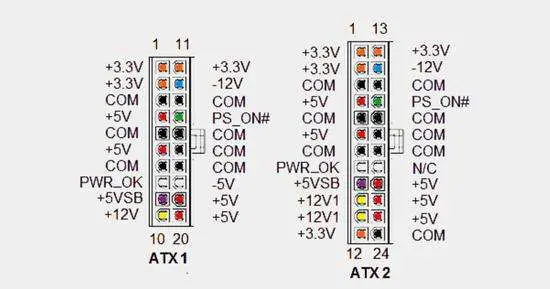
Follow the 24-pin connector diagram to compare the multimeter voltage reading.
Also, test the motherboard power by measuring the voltage of the PSU female power plug.
Use your multimeter to AC voltage to check the power supply voltage on the PC. Insert the red probe in the ground terminals and the red probe in the live wire port of the female plug. Terminals on the plug are marked with L(live), N(neutral), and G(ground).
Your multimeter should read around 120V or 240V in the female PC power plug. If the voltage reading is quite low, the plug is faulty, or the supply is insufficient.
Resistance Test
Now we’ll test the resistance of the pins and wires in the ATX power supply unit. Disconnect the power supply and detach the 20-24 pins connector from the motherboard
Make sure your multimeter is set to resistance(Ω), then place the black probe of your multimeter on the chassis; this will be the ground terminal.
Connect the red probe in the ground terminals (black wires) of the 20-24 pin connector. The black ground wires (in a 24-pin connector )with the chassis should have nearly 0Ω (ideal).
Then remove the red probe from the ground wires and connect them to the other colored wire pins in the connector. You should expect around 50ohm resistance in the colored wires of the 20-24 pin connector with the chassis.
How to test a laptop motherboard with a multimeter?
Set your multimeter to ohms (200 Ω) to check your laptop motherboard. Connect the black multimeter probe to the chassis and the red probe to the connector’s black(ground) pins. Resistance should be around 0 ohms. Now place the red probes in other colored wire pins in the connector. There should be around 50 voltage.
Also, check the voltage between the ground (black)wire pins and the rest of the pins. Compare the multimeter reading with the manual’s ideal range of each colored wire.
How to test motherboard capacitors?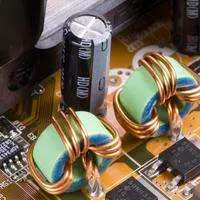
Set your multimeter to Ω(mega ohms) to test a capacitor on your motherboard. Terminals of the capacitor are soldered on the backside of the motherboard.
Connect both multimeter probes (red and black leads) to the capacitor’s positive and negative terminals(legs). Your multimeter will start reading from 0 ohms and increase up to infinity.
Caution: Don’t unnecessarily test the motherboard capacitors. Your capacitor could be charged, damaging your multimeter and shocking you if handled inappropriately. As a result, the capacitor can be discharged, and the circuit may be affected.
Conclusion
A Motherboard is tested by measuring the voltage and resistance in the 20-24 pin connector terminals. You should also visually inspect any damaged or burnt component or a loose solder connection on the motherboard.
Make sure to wear gloves before testing your PCS voltage with a multimeter. However, resistance can be measured without a power supply.
Follow the chart to understand the wire’s function, voltage, and color. Follow the simple guide above to step-by-step test your motherboard.
Related Guides: