Improve your skills with this comprehensive guide on test Diode with Analog and Digital Multimeter. Whether you’re a beginner or an experienced technician, you’ll learn step-by-step procedures to troubleshoot and identify faulty diodes. Take advantage of this valuable resource for enhancing your electronics skills.
Diodes are used while preparing a specific circuit for electric components like solar panels, LED, logic gates, and rectifiers, so diodes help the current flow in one direction. That’s why the tiny pieces called diodes are used to give a direction to the current flow in a circuit. Diodes help us to control the direction of the current in a circuit.
It is clear from the role of the diode that if it stops working or because of some damage and problem, the diode starts doing its job reversely, then it will damage the whole circuit. Because of it, the entire appliance can also get damaged, which will be a great loss for us.
So while preparing a circuit with the help of a diode, it is essential to check the diode by using the appropriate tools to know whether this diode can perform its work properly in the circuit or if you should replace it with a new and properly working diode.
What is a diode?
A diode is an electronic component that allows current to flow in one direction but not in the opposite direction. It comprises a semiconductor material with two terminals: the anode and the cathode.
When a voltage is applied to the diode in the forward direction (anode to cathode), it conducts current, allowing electrons to flow through it.
However, when the voltage is applied in the reverse direction, the diode does not conduct and blocks the current flow. This property makes diodes useful in various electronic applications, such as rectification, voltage regulation, and signal detection.
Structure of diode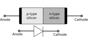
Before starting the testing procedure for Diode with Analog and Digital Multimeters, you should know about the diode’s proper structure to perform every step easily.
Diodes consist of two terminals, and they are called PN junction devices. So the two terminals are known as the cathode and anode. The difference between the cathode and anode is different in different diodes.
Still, in most diodes, the colorful terminal is called the cathode, and the other is the anode. If there is a white terminal in your diode, this is the cathode, or you can say the positive terminal of the diode, and the other one would be the anode.
By understanding the real structure of the diode now, you can easily perform the testing procedure because it is important to make a difference between the two diode terminals so that you can do the right test with them.
Working of diode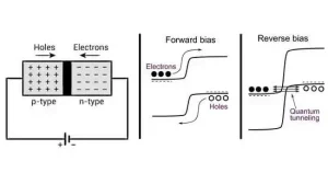
There are two conditions in which the diodes are present. It is important to know the condition of the diode before starting to test it because, in each condition, the final result will be different. The two conditions of the diodes are the following.
-
Forward biased
The diode is called the forward biased if its anode terminal is connected with the positive and the cathode terminal is connected with the neutral. In this condition, the switch is closed, and the current will start circulating in the circuit. So the diode under this condition will act as the conductor.
-
Reverse biased
The diode is called the rivers biased if its cathode terminal is connected with the negative and the anode terminal is connected with the neutral in this condition. It is called to be open, and the current will not circulate in the circuit. So the diode under this condition will act as the resistor.
There are different methods to test the diode for both of these conditions. It means you have to reverse the order of the connection after you test the forward bias setting to test the reverse bias setting of the diode.
Before going to test the diode with an Analog multimeter here first, we will test the diode with the digital multimeter below:
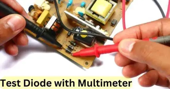
How to test diode with a digital multimeter (step-by-step guide)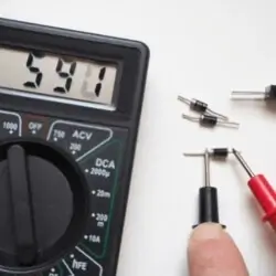
You do not have to be experienced to test the diode using the digital multimeter because it is very easy to test the diode using the digital multimeter.
After all, the digital multimeter is a very helpful tool for this purpose. For this, you will only need to put in a little effort. So by following the steps carefully, you can easily test the diode with the digital multimeter.
Step 1: Disconnect the diode
To test the diode with the digital multimeter, the first step you have to take is to disconnect the diode from the circuit so that no current can pass from the diode, and you can easily test it without any hurdle. So you have to stop the circuit’s power supply and then carefully remove the diode from the circuit and place it on the side of the circuit. Ensure no wire in the circuit is in contact with the diode.
Step 2: Set the digital multimeter
To use the digital multimeter for this purpose, you must also set it according to the type of test you will perform. For this, you have to turn the digital multimeter selection dial towards the diode symbol. Now the digital multimeter is all ready to test the diode.
Step 3: Connect the diode
Now you have to connect the diode with the digital multimeter with the help of the leads. Still, the connection will differ for both the diode’s forward and reverse-biased conditions. You have to follow both conditions one by one.
For Forward biased
If the diode is forward-biased, you have to connect the digital multimeter’s red lead with the diode’s positive terminal and the digital multimeter’s black lead with the negative terminal or cathode of the diode.
For Reverse biased
If the diode is reverse-biased, you have to connect the digital multimeter’s red lead with the diode’s negative terminal and the digital multimeter’s black lead with the positive terminal or anode of the diode.
Step 4: Note the resulting readings
You have to note the digital multimeter’s resulting readings under both conditions. Then you have to compare the results with the normal ones.
Results:
- Suppose the digital multimeter shows results around 0.6 to 0.8 for the forward-biased diode. In that case, it means that the diode is working well, and if the results are OL for the forward biased, then it means that the diode was damaged, and you have to replace it with a new one.
- Suppose the digital multimeter shows OL results for the reverse-biased diode. In that case, it means that the diode is working all well.
- Suppose the digital multimeter gives readings around 0.4 volts for both conditions. In that case, it means that the diode has got short, and now there is no chance for it to get repaired, so you have to replace it by buying a new diode.
Here is the testing procedure of the diode with an analog multimeter:
How to test the diode with analog multimeter?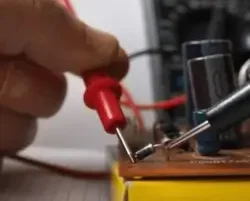
If you cannot arrange the digital multimeter or if it is convenient for you to use the analog multimeter instead of the digital one, you can also test the diode using the analog multimeter. You must follow the following guideline to test the diode with the analog multimeter.
Step 1: Turn off the power supply
Turn off any power supply to the circuit to which the diode is connected. Then you have to disconnect the diode from the circuit carefully. It is important to do this because the diode in a running circuit cannot be tested, and if you do so, you will get a shock, which will be life-threatening. So ensure you have turned off the power supply and then disconnect the diode from the circuit to test it using the digital multimeter.
Step 2: Set the analog multimeter
As you are now going to test the diode with the analog multimeter, you have to set the analog multimeter at the resistance settings. So for this, you have to turn the selection dial of the analog multimeter towards the ohm symbol, which is the symbol for the resistance. Now the analog multimeter is ready to test the diode.
Step 3: Set the range
To test the diode from the analog multimeter, it is important to set a specific range of resistance at the analog multimeter. So if you are testing a forward-biased diode, you have to set the resistance range around 1k ohms. Suppose you are testing the diode under reverse-biased conditions. In that case, you have to set the resistance range over an analog multimeter around 100k ohm.
Step 4: Connect the leads
Suppose the diode is under forward bias condition. In that case, you have to connect the red lead of the analog multimeter with the anode of the diode and the black lead of the analog multimeter to the cathode of the diode.
Suppose the diode is under reverse bias condition. In that case, you have to connect the black lead of the analog multimeter with the anode of the diode and the red lead of the analog multimeter with the cathode of the diode.
Step 5: Note the readings
You have to note the resistance readings given by the analog multimeter for both the conditions, reverse and forward biased of the diode. Then you have to compare the final results with the normal ones.
Results:
- Under the forward bias condition, if the analog multimeter shows the resulting readings around 1k ohm, it indicates a healthy diode. If the resulting reading is zero or infinite, then it is an indication of a bad diode.
- Under reverse-biased conditions, the good diode will give OL results on the analog multimeter.
- If the results are the same for both conditions, it indicates a bad diode you must replace as soon as possible.
Final verdict
If you want to avoid any disastrous conditions in the future relative to your electrical appliances, then make sure that you keep them in check at regular intervals. If you have installed the diodes in any of your circuits at your home, then you have to test those diodes because if they get damaged, they can reverse the whole circuit of the current. It will lead to big damage to your electrical appliance.
Tools like analog and digital multimeters are helpful under this condition. You can test the diode using both tools easily, and you do not have to arrange many helping materials with them. So by following proper guidance on how to test a diode with an analog and digital multimeter, you can easily test the condition of the diode. Then it will be beneficial for you to make a proper decision regarding your diode.
Related Guides: